- Fri 02 May 2025
- Public
- marci
- #Reversing, #3D printing
I recently bought a toy 3D printer from Aliexpress for around 60 EUR. I like it very much, however I am missing some quality of life features that a "real" 3D printer has. This post is to document the research performed on its main board in the hope that I can do some upgrades to it in the future.
Update - 2025.05.12.
The manufacturer answered my emails and sent the original FW image and its config file. The FW actually matches byte-to-byte with the image I dumped and the config parameters look to be the same, however I was obviously missing the measurement unit and some additional comments. Also there is a mistake on line 43? I hope the printer's parser can handle that. Anyways, happy tuning if that is your thing.
Update - 2025.05.04.
- Added UART investigation chapter
- Fixed chip type in initial memory dump part
- Added bootloader stuff
- Extracted config using Ghidra script
Hardware info collection
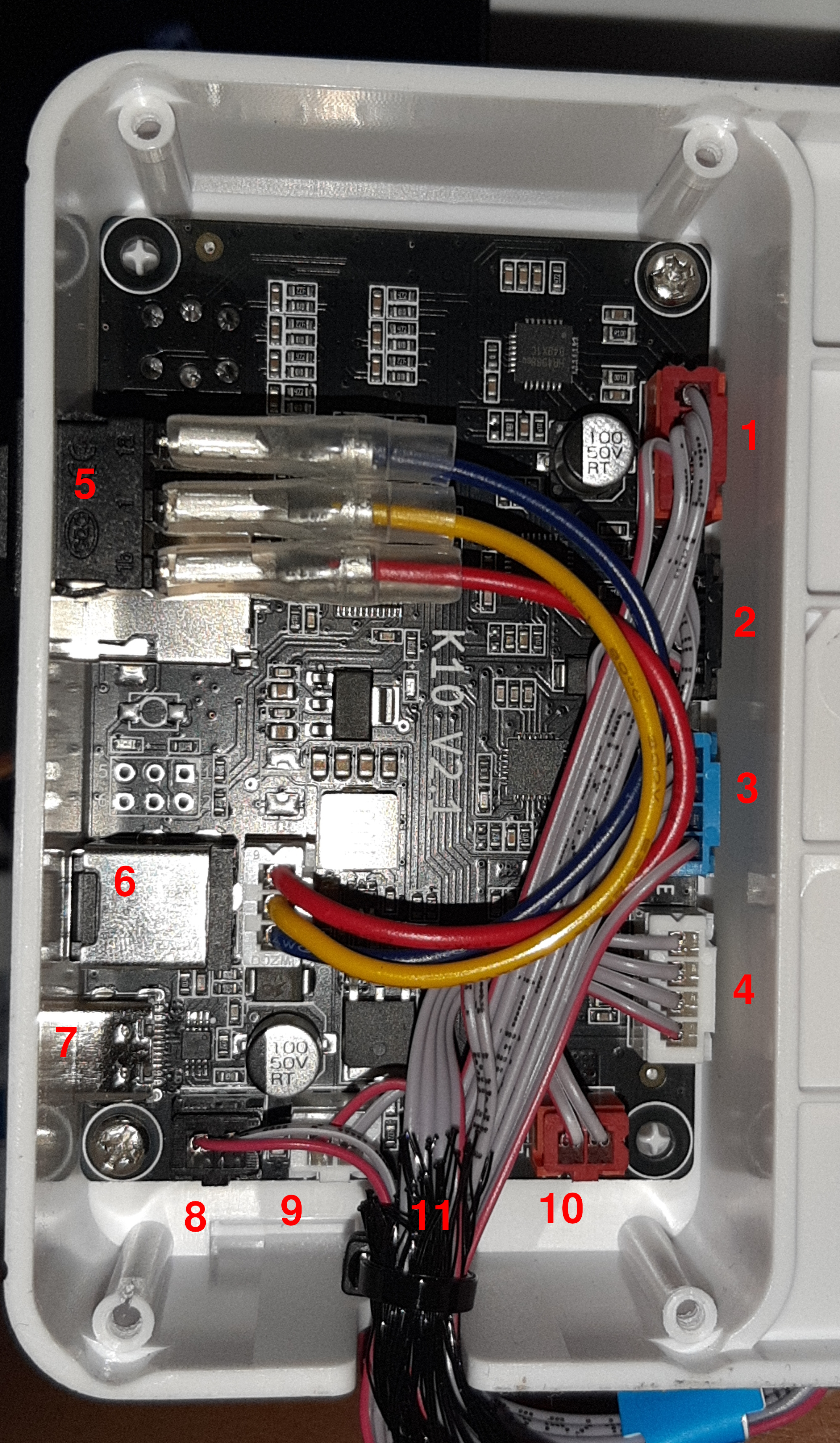
Board Wiring
- X motor
- Y motor
- Z motor
- Extruder motor
- Power switch (OFF / USB PD / DC barrel jack)
- DC barrel jack
- USB-C port
- Thermistor
- Hotend
- "VIN" ?
- Fan (hidden under the cables)
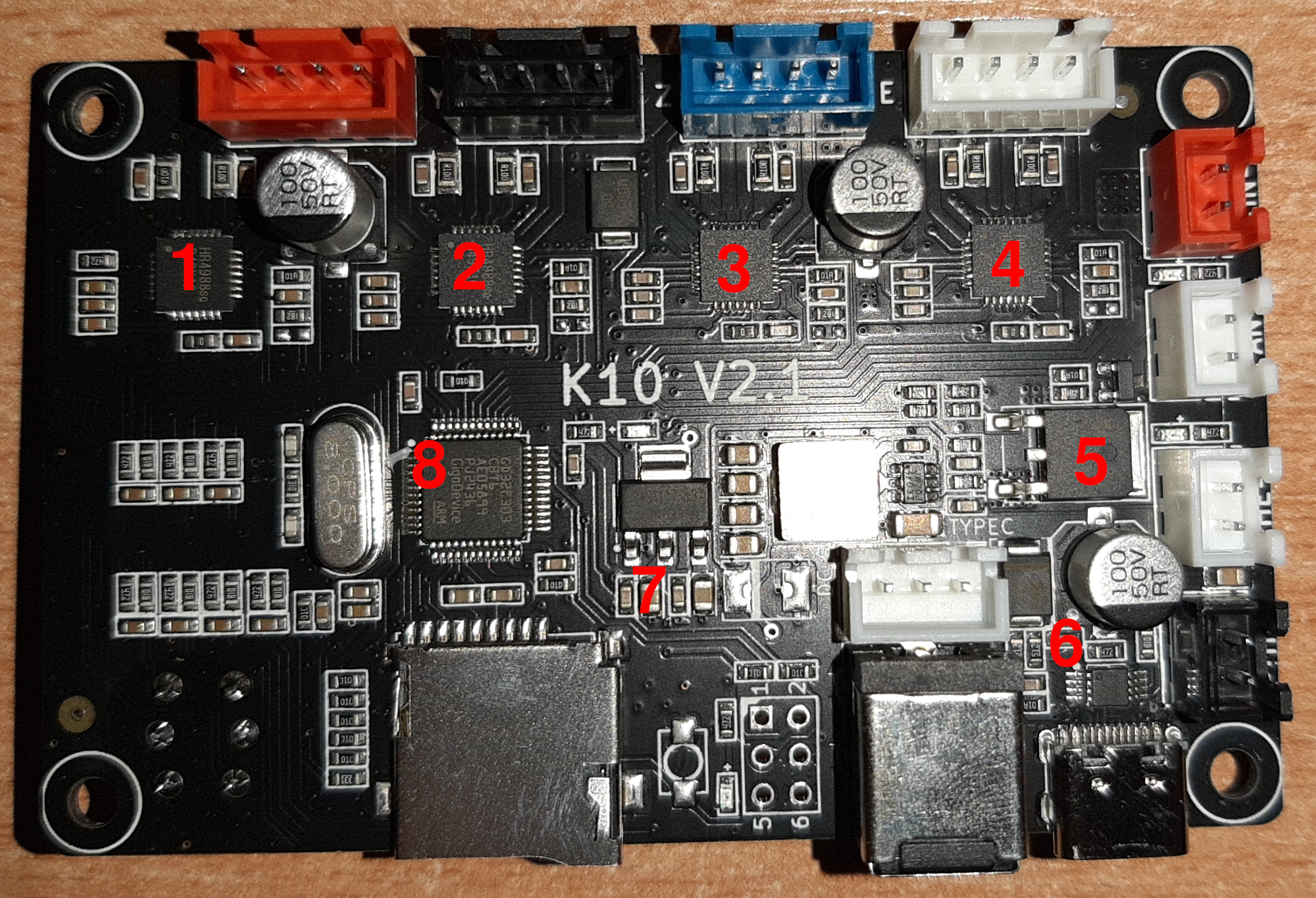
PCB top side components
- Heroic HR4988 - microstepping motor driver with built-in translator
- Heroic HR4988 - microstepping motor driver with built-in translator
- Heroic HR4988 - microstepping motor driver with built-in translator
- Heroic HR4988 - microstepping motor driver with built-in translator
- Hooyi HY1403 - N-Channel MOSFET
- Pwchip PW6606 - USB PD Sink Controller
- AMS1117 - Voltage regulator
- GigaDevice GD32F303RCT6 - Cortex-M4 Main MCU, LQFP48 package: Datasheet, User Manual
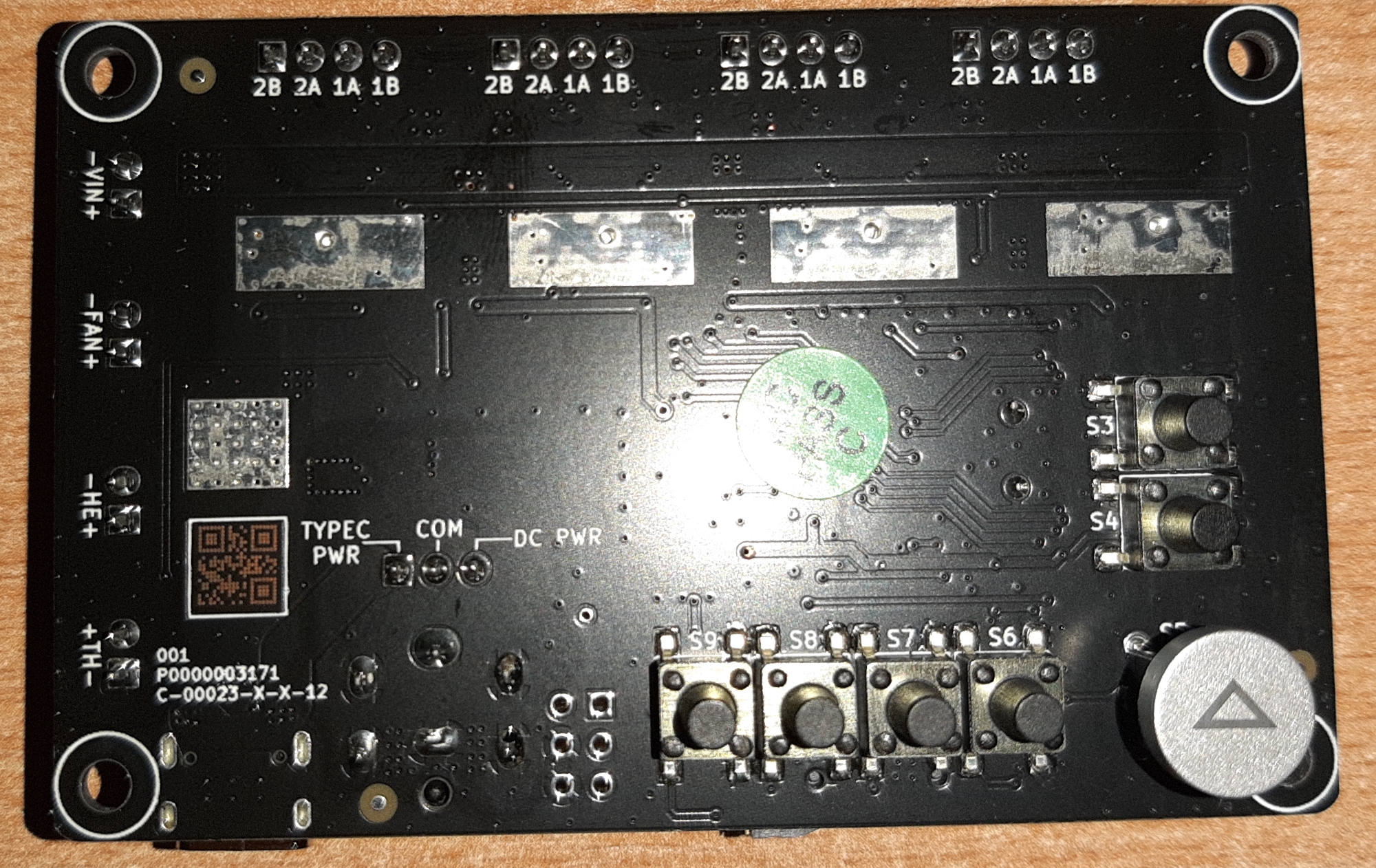
PCB bottom side buttons
- S3: Retract
- S4: Feed
- S5: Print / Lift
- S6: Position 4
- S7: Position 3
- S8: Position 2
- S9: Position 1
QR Code: M3358500713
The debug port
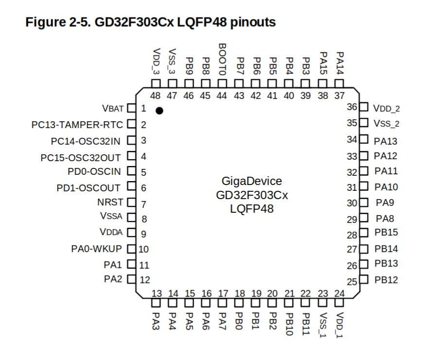
- PA13: JTMS, SWDIO
- PA14: JTCK, SWCLK
- PA15: JTDI
- PB3: JTDO
- PB4: NJTRST
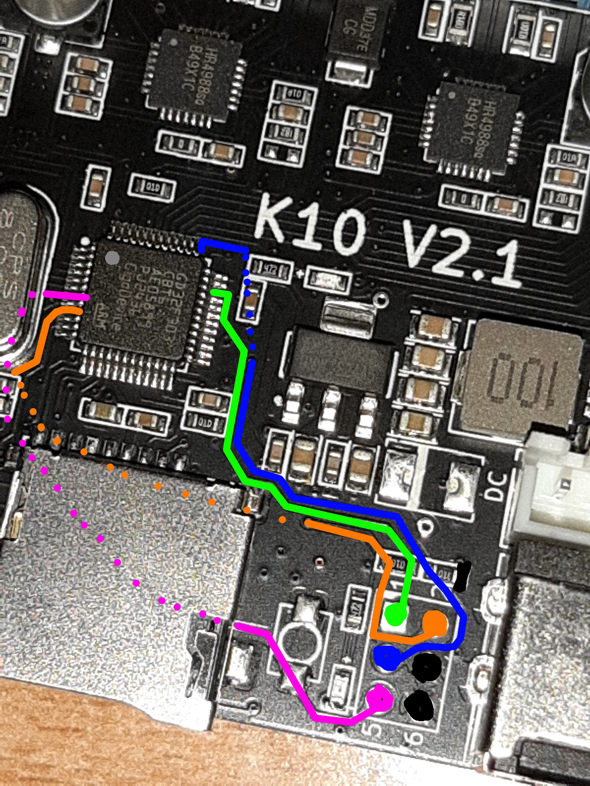
- Green: SWDIO
- Blue: SWCLK
- Orange: VDDA
- Black: GND
- Purple: NRST
The device supports "RDP" security, but only one level:
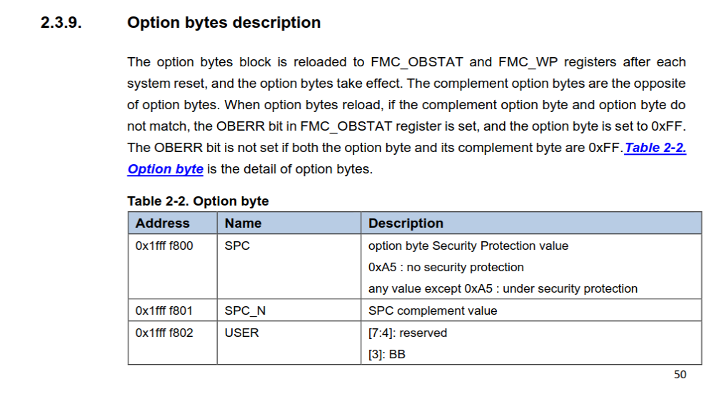
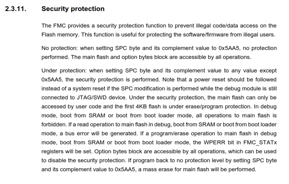
If it is set up, we should not be able to read the FW.
However, there are very cool attacks against the SWD infrastucture on the same family of chips: GigaVulnerability: readout protection bypass on GigaDevice GD32 MCUs.
But before diving in deep with hardware hacking, I wanted to check if the chip was locked or not. For a debugger I could have used a proper ARM debugger (from work :P), however I was on holiday and wanted a quick solution. That is when I found out that there is actually an open-source firmware for the Raspberry Pi Pico that can act as an SWD debugger and interface to OpenOCD running on a PC.
Dumping the FW using Picoprobe
- Download the latest UF2 release file from the repo.
- Use picotool to load it:
picotool load /home/marci/Downloads/debugprobe_on_pico2.uf2 -f - Hook up the wiring, which is: RESET = GPIO1, SWCLK = GPIO2, SWDIO = GPIO3
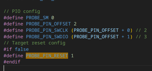
(you should connect the reset line too, because it gave me weird memory read errors without it) - Download the OpenOCD config from this repo
openocd -f interface/cmsis-dap.cfg -f gd32f30x.cfg- Connect to
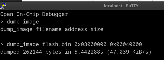
localhost:4444via telnet - Because we have an "CB" chip which has 128k of flash, we can dump it using:
dump_image flash.bin 0x08000000 0x00020000(please ignore the incorrect size on the screenshots)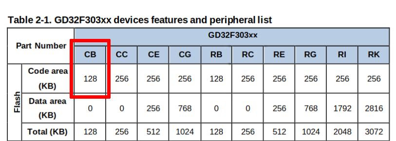
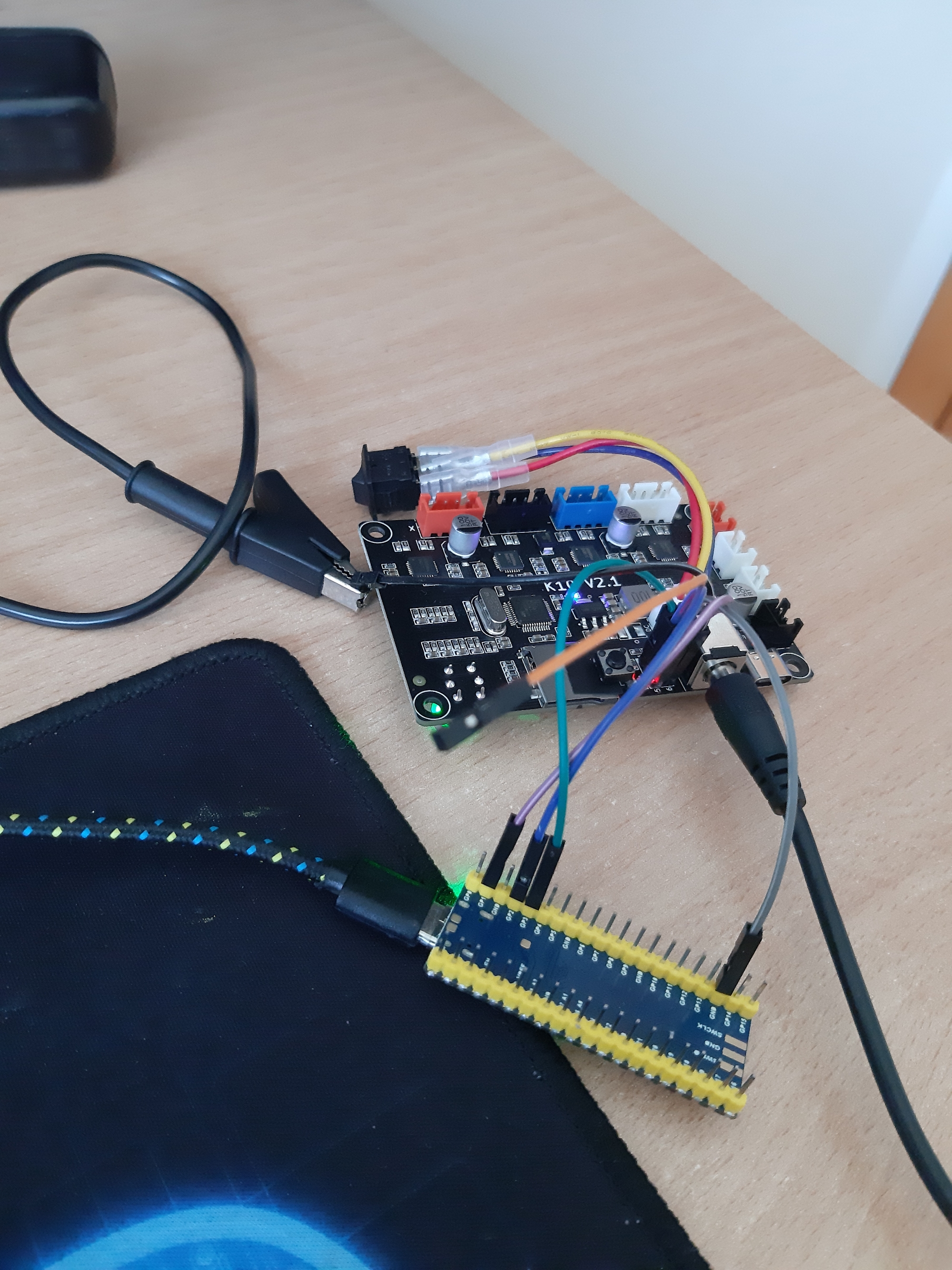
This is how the setup looked in real life:
Analyzing the FW
I loaded the FW dump in Ghidra using the Cortex Little endian config. Make sure you load the dump at the correct memory address though!
Next, I loaded the chips memory map and registers using the SVD loader Ghidra plugin. I found the SVDs online in this GitHub repo. I used the larger file from the two.
After that, the real job could begin which was to look at bare metal assembly. The data values were in between actual functions, because the chip does not have real data flash, and all of those accesses were done using double pointers by the compiler, which was not pleasant. Luckily, there were some debug strings and human-readable data which almost immediately signaled to me that this FW is actually a port of an open-source 3D printer project, called Marlin.
Because of this, instead I shifted my focus to getting Marlin compiled to this chip (using the BOARD_CREALITY_V422_GD32_MFL board settings) and generating a Function ID Database. My theory was that I could get a debug ELF out of the publicly available Marlin FW, which then I could generate a Function Database that contains function names and instruction patters that can be scanned for on the bare metal image. Sadly, this did not yield results because I think they used a different HAL implementation, the compiler might not have been the same, different optimization and debugging was enabled and the actual PCB layout was too different (GPIO & port config, different clocking, non-existent motor drivers, ...). The FW is also I think heavily modified (or at least outdated and customized a little :P).
For fun I tried debugging the thing with T32 and it worked flawlessly. I could use breakpoints and even the external reset was detected If i pressed a button which I soldered to the board. 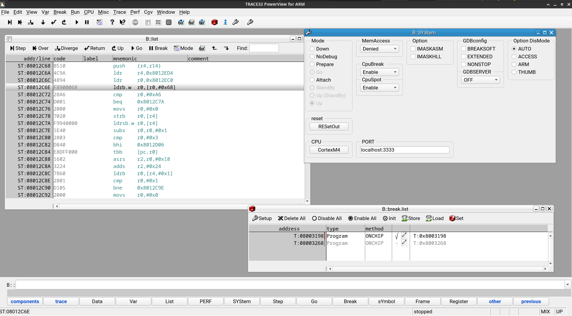
Understanding the FW
After reading this Japanase blog post, it became clear what the FW can do.
It will look for specific files on the SD card and will update the FW / configuration data:
-
p10_printer.bincan update the FW and it will be loaded to flash at offset0x4000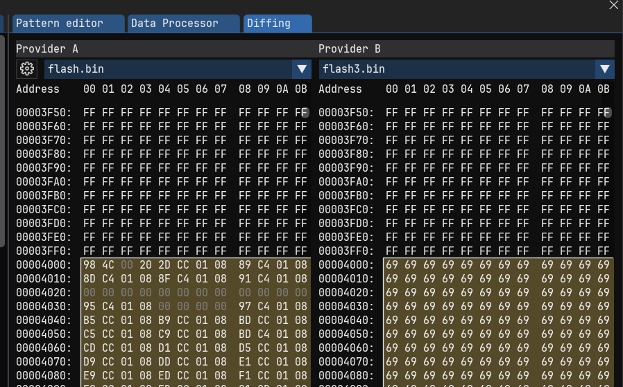
-
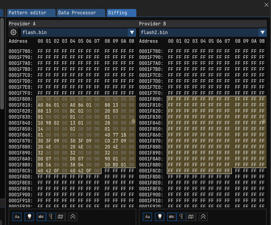
k10_cfg.txtwill update the configuration fields and it is stored in flash at offset0x1F800
If any flashing process was successful, then the file is renamed to its original name, but with a .CUR suffix, indicating that it is now currently on the device.
Before using your printer you obviously need to flash back the original firmware, which can be found here.
Configuration fields
I could not find any official configration settings, however there is a config file online for the K9 model (right before this one). I guess they are mostly the same, but it contains some additional info.
The config handling (in FUN_08008f80) works the following way: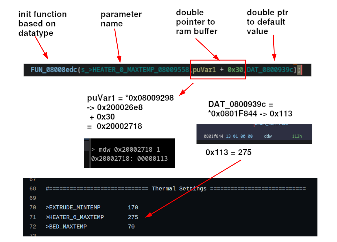
The config cfg_hardware_test_enable is special and comes from some weird TIMER3 register (CH0CV)? I don't know why this is.
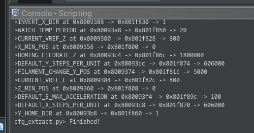
Anyways, the config extraction can be automated very easily using a Ghidra script. The output of that can be found here:
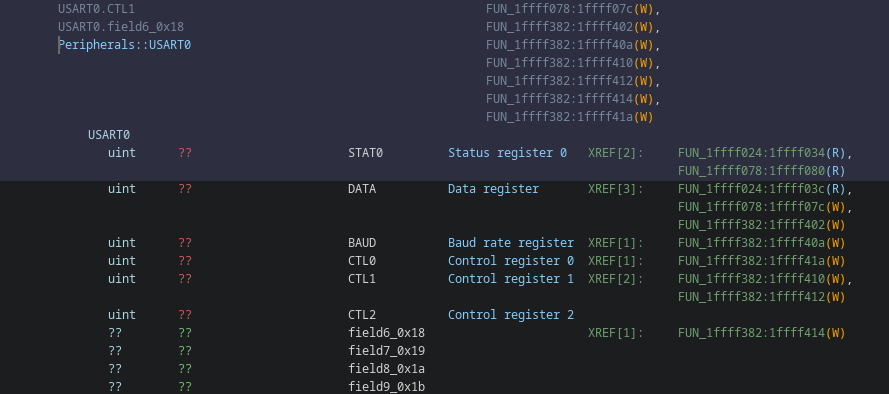
UART
There is a function (at 0x080030c8) that does something with the USART0 peripheral, however it is not executed during normal operation. Also, none of the UART peripheral seems to be enabled, this can be checked with the register at offset 0x0c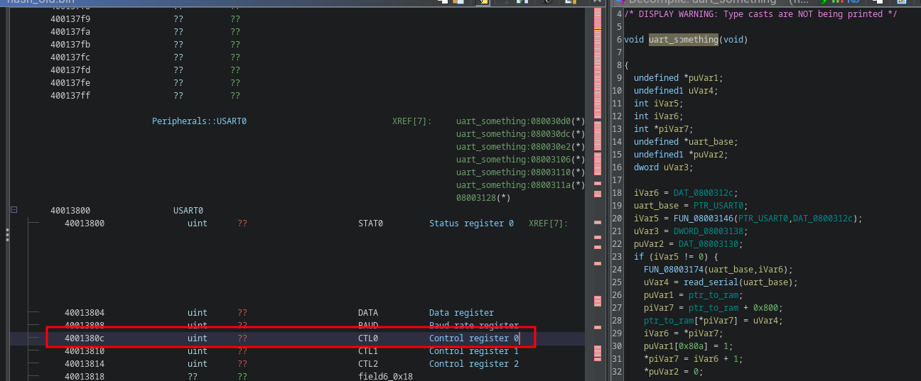
The read/write breakpoints also do not break on access to the UART data register, but when I manually put the PC to that weird function I mentioned earlier, it triggers a halt. But then why is that function there with 0 references? I thought it may be related to some kind of bootloader, however I found out that the chip already has a (baked in?) bootloader at 0x1FFFB000 - 0x1FFFF7FF. Dumping it out and disassembling it I can see nice register references to the UART, which is mentioned in the datasheet.
So, concluding:
- no UART to USB chip is present on the board
- the UART pins are not connected on the PCB or routed to to the motor drivers (alternate pins)
- the FW does not seem to enable any of the UART peripherals
- FW dissassembly indicates no references, only some dead code that does nothing much really
Conclusions
The PCB design is not bad, however there are a few components (reverse protection diodes?) not populated. The Marlin FW supports the main microcontroller and even the motor drivers. We have full JTAG access with working debugging, therefore it would be not that hard to port and run Marlin for the device. We also have SD card FW update, which would make it much more available for the average user. However, the gains are not that high, since the PCB is not that expandable. I think we could have USB serial G-code loading and maybe autolevel / proper end stop switch support, because there are a few unused pins, however that would require full 2 layer PCB reversing with uncovering the full pinout and then porting Marlin to it. It also would require SMD (or at least very precise) soldering directly to the MCU pins (if they are not grounded or something).
Also, cheap 3D printer motherboards are available with native Marlin support, however that may be overkill for such a cheap device.
One interesting outcome of this investigation (for me at least) is the SD card config support, however I don't know if those values are worth fiddling with.